We're sorry. The shop is temporarily closed. All orders will be sent after 15th of January.


StepperServoCAN
258,00 zł
Stepper motor closed-loop control board with CANbus
PCB + magnet + M3 bolts + 3d printed ABS cover + 100cm power/debug cable.
Note:
this Item can be purchased only by private customers.
Out of stock
This two-phase motor stepper control board has a unique set of features: closed-loop commutation, CANbus networking, and open-source. It is specifically suited for low-cost but robust robotics where interaction with the user and variable load is present (steering, pedal, robot arm actuators). It provides smooth, low-noise torque delivery and the ability to be overcome and reversed by an external torque. The controller is designed to not cause resistance when the motor is rotated externally and the control is disabled.
The controller board fits Nema17 and Nema23 bolt patterns and can be installed directly on the back of the motor and its height is only 8 mm. Additionally, if Nema23 support is not necessary, the side tabs of the PCB can be broken off and PCB size reduced.
The heart of the controller is a magnetic sensor with a diametrical magnet attached to the stepper shaft under the board. The magnetic field penetrates the thin PCB composite and is measured by the angle sensor chip. To increase accuracy and to compensate for any magnet misalignments the control performs initial calibration by doing rotation back and forth. More information about that process is in the firmware section.
Low current consumption allows the controller to be always powered and continuously keep track of zero angle and multiples of full rotations.
Input/output characteristics:
- Supply voltage: 9-30V
- CANbus (compatible with both 3.3V and 5V)
- SWD Debug port (3.3V)
- Motor max output:
- (continuous) 3.3A RMS driving current
- (1s) 3.3A peak stall current per phase
Functionality:
- The board can be used to drive one stepper motor or two DC motors
- High-precision position reading of a stepper motor
- The board can be broken apart and converted from Nema23 to Nema17 if space is a constrain
- Freewheeling with overvoltage protection
- CANbus transceiver
- Two function buttons and a reset button
- Debug port for flashing and configuration (with ESD protection)
- (Optional) Enable port with hardware interrupt capability and ESD protection.
- Reverse polarity and voltage spike protection
- Optional jumper pads, e.g. for multi-motor identification
Sensors:
- Magnetic angle sensor
- Current (Low-side),
- Motor driver voltage
- Battery driver voltage
- PCB temperature
Size: Nema17 / Nema23
56mm x 40mm (+2.7) x 8mm (l/w/h) – see the picture
Connectors type:
- 4pin JST XH 2.5mm (Car, Debug, Motor – electronically protected against wrong insertion)
- 2pin terminal 2.5mm (Enable pin) – not provided – needs to be soldered manually
Firmware:
PCB will come flashed with the latest build of:
https://github.com/dzid26/StepperServoCAN
Controller kit includes:
- 1x – PCB
- 1x ABS cover
- 1x – magnet (2mm height / 6mm diameter)
- 2x – M3 bolts (~35mm P
hilips) - 2x – M3 bolts (~40mm Allen)
- 1x Power / Debug cable – 100cm, (4pin JST on both sides, high-current)
The included cover is made of 3D-printed ABS plastic and bolted together with the PCB thru oversized brass inserts.
Warning:
This is an engineering development kit and is sold as-is without any warranties. While the product was designed with robustness and safety in mind, any accident or damage caused by this product is at the buyer’s own risk.
Related products
-

A1/C3X/C3 lenses
236,50 złSelect options This product has multiple variants. The options may be chosen on the product page -
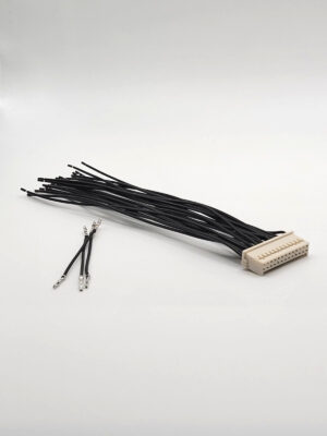

Open Pinout harness cable
124,70 zł -
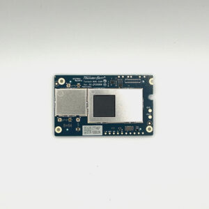

Thundercomm D845 SOM 8GB+64
903,00 zł -
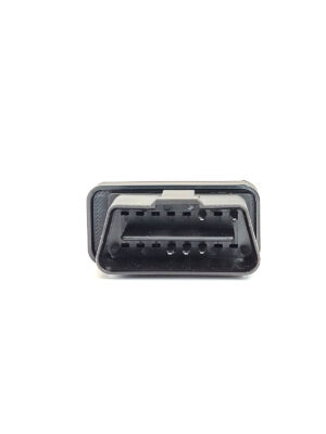

OBD Power
64,46 zł – 85,96 złSelect options This product has multiple variants. The options may be chosen on the product page